A cast-in anchor channel is a C-section steel profile with welded anchors, embedded during the pour with the channel mouth flush to the concrete surface. After cure, T-bolts slide in from either end, rotate 90° to lock under the channel lips, and accept façade brackets, curtain-wall mullions, MEP rails, secondary steelwork or fall-arrest anchorage — with stepless adjustment along the slot and no drilling into cured concrete. This guide covers hot-rolled versus cold-rolled profiles, T-bolt selection, load capacity and failure modes under EN 1992-4 / ACI, edge distance, corrosion protection and a 10-step installation.
1. What a cast-in anchor channel is
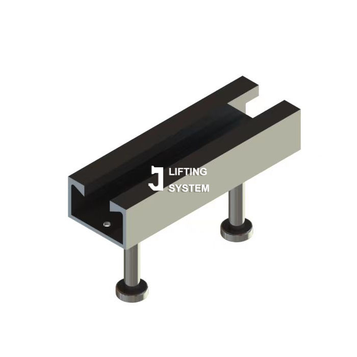
A cast-in anchor channel is a C-section steel profile with welded anchors that is embedded in concrete during pouring, with the channel mouth flush to the concrete surface. After cure, T-bolts slide into the channel from either end (or are dropped into a pre-cut keyhole), are rotated 90° to lock under the channel lips, and accept any structural connection — façade brackets, curtain wall mullions, MEP rails, secondary steelwork, signage, fall-arrest anchorage.
The product family has been on the market since the 1950s, and its toothed C-section geometry is now the de-facto global standard. Chontan manufactures the full range in its CIC-HR (hot-rolled) and CIC-CR (cold-rolled) lines.
The reason this product category exists — and why every façade contractor specifies it — is operational, not just mechanical:
- Adjustability along the channel. A 600 mm channel accepts a T-bolt anywhere along its length, infinitely positioned without drilling. A drilled mechanical anchor commits to one location forever.
- No concrete drilling on site. All anchoring is in the precast plant or during the concrete pour. Site labour just slides a T-bolt and torques a nut.
- Reuse and repositioning. If a curtain wall mullion needs to move 50 mm during commissioning (and it always does), you slide the T-bolt — you don't drill new anchors.
- Tested system performance. Both the channel and the matched T-bolt have been pull-tested as one assembly. A drilled anchor depends on installer skill; a channel depends on factory geometry.
2. Hot-rolled vs cold-rolled — the single most important decision
Cast-in channels come in two manufacturing routes that produce two fundamentally different products:
| Hot-rolled (HR) | Cold-rolled (CR) | |
|---|---|---|
| Process | Solid steel bar heated to 1,150 °C and rolled to C-profile in one pass | Sheet steel bent to C-profile at room temperature |
| Wall thickness | 5–9 mm | 2–4 mm |
| Channel lip geometry | Toothed / serrated — interlocks with T-bolt teeth | Smooth — relies on T-bolt friction |
| Static load capacity | Up to 72 kN per T-bolt | Up to 18 kN per T-bolt |
| Dynamic / seismic load | ✓ Permitted | ✗ Not permitted |
| Typical use | Curtain wall mullion anchorage, façade dead load, MEP rails carrying equipment | Rainscreen sub-frame, signage, light cladding, secondary handrail |
| Chontan range | Chontan CIC-HR | Chontan CIC-CR |
| Indicative cost ratio | 1.0 × (baseline) | 0.4 × (60% cheaper per metre) |
3. Anatomy and the T-bolt mechanism
The five load-transfer interfaces
- Bracket → Nut: friction + bearing under washer.
- Nut → T-bolt: thread engagement (typically M12, M16 or M20).
- T-bolt teeth → Channel lip teeth: form-fit interlock (hot-rolled only) or friction (cold-rolled).
- Channel body → Welded anchors: tested-and-certified weld.
- Anchors → Concrete cone: bearing of anchor head on surrounding concrete.
Any one of the five can fail under load; the channel SWL is the smallest of the five capacities, divided by the safety factor. See §5.
4. Standards: EN 1992-4 and ACI 318
Cast-in channels for structural use should be specified against a recognised design and corrosion standard. Reference the following in your spec:
| Standard / Document | What it governs | Why it matters |
|---|---|---|
| EN 1992-4 | Design of fastenings for use in concrete, including anchor channels | Defines the design method for steel-side and concrete-side resistance per anchor and per T-bolt. |
| ACI 318-19 Appendix D | Concrete-side capacity (cone, side blow-out, splitting) | The US / international equivalent for concrete capacity calculation. Used in tandem with steel-side from EAD. |
| ISO 1461 | Hot-dip galvanizing thickness ≥ 45 μm | Sets the corrosion protection floor. Outdoor channels without HDG fail within 5–10 years. |
| ASTM A123 | HDG for North American market | Equivalent to ISO 1461 with slightly different testing protocol — accept either. |
| EN 10204 3.1 | Mill certificate format | The only cert grade an independent QA can audit against heat / batch number. |
5. Load capacity and the five failure modes
Channel SWL is governed by the smallest of five failure paths:
- F1. T-bolt rupture — bolt tensile failure (M12 class 8.8 ≈ 50 kN ultimate).
- F2. Channel lip pull-out — channel lip bends open under bolt head tension. Unique to anchor channels; doesn't exist in solid anchors.
- F3. Anchor weld rupture — fillet weld at anchor-to-channel joint fails.
- F4. Concrete cone — concrete pulls out around the anchor head.
- F5. Concrete edge breakout — concrete spalls between anchor and panel edge.
Worked example: Chontan CIC-HR 40/22 in C25/30 concrete with M16 class 8.8 T-bolt
Channel: hot-rolled, 40 × 22 mm C-profile, 6 mm wall, two welded round anchors (Ø 12 mm, h_ef = 95 mm), 250 mm spacing, edge distance a_R = 100 mm.
- F1 T-bolt: M16 class 8.8 stress area 157 mm², UTS 800 N/mm² × 157 = 126 kN. γ = 3.0 → allowable 42 kN.
- F2 Lip pull-out: Per the manufacturer's test data, hot-rolled 40/22 channel rated 36 kN per T-bolt. γ already applied. → 36 kN.
- F3 Weld: 6 mm fillet weld around Ø 12 anchor, weld length ≈ 38 mm, shear stress allowable 220 N/mm² → 50 kN. → 50 kN.
- F4 Concrete cone: N_Rk,c = 7.5 × √25 × 95^1.5 = 34.7 kN. γ_c = 2.5 → 13.9 kN.
- F5 Edge breakout (a_R = 100 mm < h_ef = 95 × 1.5 = 142 mm): apply reduction factor 0.7 → 13.9 × 0.7 = 9.7 kN. ← governs
Per-bolt SWL = min(42, 36, 50, 13.9, 9.7) = 9.7 kN ≈ 0.99 t. To raise SWL to design-load 15 kN, move the channel inward to a_R ≥ 142 mm (eliminates F5 reduction) — new SWL = 13.9 kN ≈ 1.4 t. Or increase embedment by switching to CIC-HR 50/30 with h_ef = 120 mm → concrete cone 49 kN, full F4 = 19.6 kN, full F5 = 19.6 × 1.0 = 19.6 kN, SWL = min(42, 36, 50, 19.6, 19.6) = 19.6 kN ≈ 2.0 t.
6. Chontan CIC-HR — key specifications
| Parameter (40/22 class) | Chontan CIC-HR 40/22 |
|---|---|
| Channel geometry standard | Toothed C-section |
| Channel wall thickness | 6.0 mm |
| Anchor type | Round bar Ø 12 mm, h_ef 95 mm |
| Rated SWL per T-bolt | 36 kN |
| Channel lengths available | 150 – 6,000 mm + custom |
| Standard finish | HDG ≥ 55 μm, A4 stainless |
| EN 10204 3.1 cert | ✓ default |
| Indicative FOB price (1k metre lot) | USD 5.20 – 7.80 / m |
| Lead time | 25 – 40 days |
| OEM private label | ✓ from 2,000 m |
For a curtain wall contract using 50,000 m of channel a year, China-direct sourcing delivers a substantial cost saving before freight. With Chontan test reports and EN 10204 3.1 certs on every shipment, the structural-engineer acceptance path is fully documented.
7. How to specify the right channel in five questions
- Load type? Static + secondary → cold-rolled OK. Dynamic / seismic / structural → hot-rolled mandatory.
- Peak design load per T-bolt? Look up the smallest channel that delivers SWL ≥ design load with your edge distance and concrete strength.
- Edge distance available? < h_ef → upsize channel or move inward. ≥ 1.5 × h_ef → full SWL.
- Channel length? Field-adjustability requirement drives this. 300–500 mm for curtain wall typical; 600–1000 mm for MEP rails.
- Exposure class? Interior dry → zinc plate. Exterior + freeze-thaw → HDG ≥ 55 μm. Coastal < 1 km from sea → A4 (316) stainless.
8. Edge distance, spacing and embedment
Anchor channels have three edge distances to check — more than a single cast-in anchor:
- a_e (longitudinal): distance from the channel end to the panel edge (parallel to channel axis). Typically ≥ 50 mm.
- a_R (transverse): distance from the channel mouth to the nearest perpendicular panel edge. Drives concrete-side capacity (F5).
- a_a (between anchors): centre-to-centre spacing between welded anchors along the channel. Manufacturer-fixed at typically 150 mm or 250 mm.
| Condition | SWL factor | Mitigation |
|---|---|---|
| a_R ≥ 1.5 × h_ef (typical 140 mm) | 1.00 | — |
| a_R = 1.0 × h_ef | 0.85 | Verify per datasheet |
| a_R = 0.5 × h_ef | 0.55 | Add U-bar tail reinforcement |
| a_R < 0.5 × h_ef | not permitted | Special engineering |
| a_e < 50 mm | 0.70 | End cap mandatory + move inward |
| Concrete f_c at lift = 20 MPa (vs 30 MPa rated) | 0.82 | Delay loading 7 days |
9. 10-step installation procedure
- Verify channel model against drawing — size, length, finish, anchor type. Reject any channel missing the laser-etched system mark.
- Verify foam plug condition inside the channel — must be intact and seated, no concrete-ingress path.
- Position channel on formwork at drawing coordinates. For nail-on plate: nail the perforated plate to the formwork face at minimum 4 points.
- Verify anchor orientation — anchors point away from the formwork (into the concrete body).
- Place reinforcement around the channel anchors — at least 2 stirrups crossing the anchor zone.
- Pour concrete per normal practice. Vibrate AWAY from the channel — direct vibration can dislodge the foam plug.
- Cure to f_c per the channel datasheet (typically 25 N/mm² minimum for full SWL).
- Strip formwork. Remove nail-on plate — pry away from the channel mouth, not toward it.
- Remove foam plug by hand or compressed air. Inspect channel interior — clean, no concrete residue, lip teeth (if hot-rolled) intact and undamaged.
- Install T-bolt — insert from channel end, slide to position, rotate 90° to lock. Verify engagement mark visible on bolt head. Torque the nut to the manufacturer-specified value (typically 40–80 Nm depending on bolt size).
10. Corrosion protection — match channel and T-bolt
Channels and T-bolts must have matched corrosion classes to avoid galvanic cells:
| Exposure | Channel finish | T-bolt finish | Expected service life |
|---|---|---|---|
| Interior dry (warehouse, office) | Zinc plate 8 μm | Zinc plate 8 μm | 50+ years |
| Interior wet (basement, pool) | HDG 55 μm | HDG 55 μm | 50 years |
| Exterior temperate (façade) | HDG 55 μm | HDG 55 μm | 40–60 years |
| Coastal (< 1 km from sea) | Stainless A4 (316) | Stainless A4 (316) | 60+ years |
| Industrial / chemical exposure | Stainless A4 (316L) duplex 2205 | Duplex 2205 | 40+ years |
Never mix HDG channel with stainless T-bolt in exterior environments — the galvanic potential difference creates accelerated zinc corrosion at the lip-bolt interface. If the budget only allows stainless on one component, put it on the channel (more steel mass, harder to replace).
11. Procurement & cost optimisation
For a façade contractor running 50,000 m of channel per year, total spend is USD 250K – 1.3M depending on brand. Three levers move that meaningfully:
- Standardise channel sizes. Most contractors drift into 4–6 channel sizes. A spec review usually finds 2–3 cover 90% of brackets. Each size consolidated saves 5–8% on unit price.
- Match T-bolts to channel manufacturer. Cross-brand sourcing voids the matched-system warranty and tested resistance. Buy channel + T-bolt + nut from one supplier.
- Bulk-buy on annual contract. 80,000 m blanket order vs 10,000 m spot purchase typically drops FOB China price by 18–25%. Chontan price ladder: 5k m / 20k m / 80k m / 200k m.
12. Frequently asked questions
What is a cast-in anchor channel?
A C-section steel profile with welded anchors that is cast into concrete with the channel mouth flush to the concrete surface. After cure, T-bolts are slid into the channel and rotated 90° to lock; they accept structural connections (façade brackets, curtain wall, MEP rails, secondary steelwork). The channel-and-T-bolt assembly forms an infinitely adjustable position along the channel length without drilling into the cured concrete.
What is the difference between hot-rolled and cold-rolled anchor channels?
Hot-rolled channels (Chontan CIC-HR) are forged from solid bar at elevated temperature — they have toothed or interlocking channel lips that mechanically engage the T-bolt under shear, and carry static, dynamic and seismic loads. Cold-rolled channels (Chontan CIC-CR) are formed from sheet steel — they are 30–40% cheaper but limited to static loads on secondary connections (rainscreen, signage, light cladding).
How is the load capacity of an anchor channel determined?
Load capacity is the minimum of five failure modes: (1) T-bolt tensile rupture, (2) channel lip pull-out (lip bending failure), (3) anchor steel rupture, (4) concrete cone pull-out, (5) concrete edge breakout. The governing mode depends on channel geometry, anchor spacing, edge distance, concrete strength and applied load direction. Use the manufacturer's design software (Chontan ChannelDesign) or hand-check per EN 1992-4 and ACI 318 App. D.
What standards govern cast-in anchor channels?
Key references include EN 1992-4 (anchor channel design), ACI 318-19 Appendix D (concrete-side capacity), ISO 1461 (HDG corrosion protection ≥ 45 μm), ASTM A123 (North American HDG) and EN 10204 3.1 (mill certificate). Specify the channel and T-bolt as a matched system with documented design resistance per anchor and per T-bolt.
What is the minimum edge distance for a cast-in channel?
Minimum edge distance is typically 0.5 × h_ef (anchor embedment depth) at the channel ends and 1.5 × h_ef between adjacent anchors along the channel. For full SWL, edge distance ≥ h_ef is required. Closer to the edge, the manufacturer's reduction factors apply (typically dropping SWL to 0.55 at 0.5 × h_ef edge distance). Channels parallel to a concrete edge are especially sensitive — always run the channel perpendicular to the edge when possible.
What is the T-bolt 'engagement mark'?
A line or arrow on the head of the T-bolt that becomes visible only when the bolt is rotated 90° into the locked position inside the channel. The mark gives the installer a binary go/no-go check — if you can't see the mark, the bolt is not locked. Reject any T-bolt that doesn't have one.
How are anchor channels installed in formwork?
Three methods: (1) Nail-on plate — the channel is delivered with a perforated steel plate on its mouth that nails to the formwork face; cheapest and most common for precast plants. (2) Magnetic — magnets on the channel back hold it to the steel formwork; reusable but expensive. (3) Foam filler — a foam strip in the channel cavity prevents concrete ingress while leaving the channel mouth clean after cure. Always seal the channel ends with end caps to prevent concrete entering from the side.
How long is a typical anchor channel?
Standard channels are supplied in lengths of 150 mm to 6,000 mm. For curtain wall and façade applications, 300–800 mm is most common. For long continuous façade rails, two or more channels are butted end-to-end with end caps; the joint is non-structural so loads must transfer entirely through the T-bolt connection above or below it. Custom lengths and bends are available from Chontan from 1,000-piece MOQ.
What corrosion protection should I specify?
For interior dry applications: zinc plating (5–8 μm) on channel and T-bolt is sufficient. For exterior façade or coastal: hot-dip galvanized HDG ≥ 45 μm (per ISO 1461) for both channel and T-bolt; stainless A4 (316) for coastal within 1 km of seawater. Mixing dissimilar metals (e.g. galvanized channel + stainless bolt) is OK but specify a sealing washer at the bolt head to prevent galvanic corrosion at the interface.
References
Who wrote this, and why you can check it
We make these parts, we don't resell them
Qingdao Chontan Industry has been supplying the precast and prestress industries for over 20 years, from our own factory in Chengyang District, Qingdao. Everything in these guides comes from producing, testing and shipping the components they describe — not from a catalogue.
Our own test floor, not an outsourced claim
Anchors are verified in-house before they leave:
- 30 T – 300 T universal tensile testers for pull-out and tensile testing
- Low-temperature impact testing — the test that catches brittle behaviour
- Metallographic structure analysis and hardness testing
- Material sampled for microscopy before the first manufacturing operation
- Dimensional inspection against drawings, with purpose-made gauges during production
Facts are attributed to the standard, not to us
Where these guides quote a limit — a load, a wear limit, an inspection interval, a cover formula — it is attributed to the standard that sets it (EN 1992, EN 10204, EN 13101, DIN 405, VDI/BV-BS 6205, ACI 318, the Machinery Directive). We tell you which document to read, so you never have to take our word for it.
What we will not do
- We do not publish another manufacturer's load tables as our own data.
- We do not quote a rating without its conditions — concrete grade, embedment, edge distance.
- Illustrative numbers are labelled illustrative; design from your supplier's tested data.
- Where we are uncertain, we say so and point you to the primary source.
Need DIN-compatible anchor channels at China-direct prices?
20+ years export experience. Hot-rolled + cold-rolled, full range 22/14 to 72/49. EN 10204 3.1 certs included. MOQ from 500 metres. We'll quote against your drawing in 24 hours.