A spherical head lifting anchor is a cast-in steel anchor with a forged ball-shaped head that mates with a universal lifting clutch — originally the German “Kugelkopfanker”, with its head geometry codified in CEN/TR 17081 and now the de-facto global interface between precast elements and rigging hardware. Safe working load is the smallest of the steel-rupture, concrete-cone and edge blow-out failure paths divided by the safety factor, and the concrete side almost always governs. This guide covers the standard that fixes the geometry, how SWL is actually derived, edge distance and spacing rules, the failure modes, and a 12-step installation procedure.
1. What a spherical head lifting anchor is
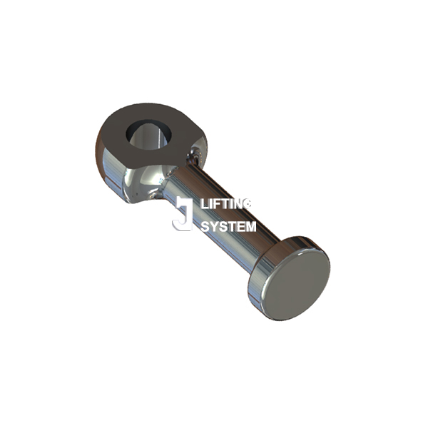
A spherical head lifting anchor is a cast-in steel anchor whose distinguishing feature is a forged ball-shaped head that mates with a universal lifting clutch. The system originated in Germany in the 1970s as the "Kugelkopfanker" (ball-head anchor), and its standardized head geometry — later codified in CEN/TR 17081 — has since become the de-facto global interface between precast elements and the rigging hardware that lifts them.
Today, almost every precast plant in Europe, North America, Japan and the Gulf uses a variant of this design, including the standard-geometry units manufactured by Chontan.
The appeal is operational, not just mechanical:
- One clutch, every anchor size. A universal lifting eye in the 1.3 t, 2.5 t, 5 t, 10 t or 20 t class engages every anchor of that capacity — regardless of manufacturer — because the head geometry is standardized.
- Snap-lock engagement. The rigger slides the open clutch ring over the head, rotates 90°, and the spring-loaded retaining pin clicks shut. No threading, no torque wrench, no removable bolt.
- 360° rotation under load. The ball-and-socket joint lets the clutch swivel during a tilt-up, so the rigger doesn't need to re-orient the precast.
- Flush finish. After demoulding, the recess former leaves a smooth conical pocket that can be patched with non-shrink grout — no protruding hardware to grind off.
2. Anatomy of the spherical head lifting system
A working installation has five physical parts, three permanently cast in the concrete and two temporary on the rigging side:
The three parts that live inside the concrete drive 95% of the engineering decisions:
- Head (①) — A spherical or sphero-conical forging whose dimensions (head diameter d_K, neck diameter d_n, head height h_K) follow the standard head geometry. The clutch interfaces only with these three dimensions; anything else can vary between manufacturers.
- Shank (②) — A round bar that transfers tensile load from the head to the foot. Cross-section is sized for the SWL class and the steel grade (typically C15E or 36CrNiMo4 quenched-and-tempered).
- Foot (③) — A flared or disc-shaped foot that resists pull-out by bearing on the surrounding concrete cone. Foot diameter d_f is the single most important variable for concrete-cone capacity.
3. The standards that actually govern this product
Several standards matter — most procurement specs cite only one or two of them, leaving room for ambiguity. Cite them all to leave bidders no wiggle room:
| Standard | What it governs | Region of force | Why it matters for you |
|---|---|---|---|
| EN 10204 3.1 | Inspection certificate format | EU | The only mill cert grade that an independent QA can audit against batch and heat number. |
| ACI 318 App. D / CEN/TR 17081 | Concrete cone capacity, edge / spacing reductions, supplementary reinforcement | USA / EU | Tells you when SWL must be derated for edge proximity and how to design tail bars when it is. |
| BGV D6 (D-A-CH) / BGR 500 | Lifting accessories — inspection intervals, retirement criteria | D-A-CH | If your buyer is in Germany, Austria, or Switzerland, the clutch (not the anchor) must carry a BGV D6 mark. |
| VDI/BV-BS 6205 | Precast-element lifting design | Germany | The dynamic factor (typically 1.3) and the dimensioning workflow that German precast engineers expect. |
4. Load capacity, SWL and the math you can show your QA
The label on a spherical head anchor — "5.0 t", "10 t", "20 t" — is its Safe Working Load (SWL), not its breaking strength. SWL is what the manufacturer guarantees the anchor will hold under defined service conditions, after every reduction factor has been applied. Two numbers govern the calculation:
- Ultimate Tensile Strength (UTS) — the load at which the anchor body fractures, measured in a notched-tensile test on the shank.
- Concrete Cone Capacity (N_Rk,c) — the load at which a cone of concrete around the foot pulls out. Calculated per ACI 318 or CEN/TR 17081.
SWL is the smaller of the two values, divided by the safety factor:
where γ_s = 3.0 (steel safety factor, precast industry) and γ_c = 2.5 (concrete safety factor per ACI 318 Appendix D for cast-in headed anchors).
Worked example: a 5.0 t Chontan SHL-50 anchor in C25/30 concrete
Anchor: SHL-50, shank Ø 20 mm, foot Ø 60 mm, embedment h_ef = 240 mm, steel grade C15E (UTS = 380 N/mm²).
- Steel side. Shank tensile area A_s = π × (20/2)² = 314 mm². UTS load = 314 × 380 = 119 kN. With γ_s = 3.0, allowable steel-side load = 39.7 kN ≈ 4.05 t. Anchor fails steel-side first at this rating.
- Concrete side. Concrete cone capacity per ACI 318: N_Rk,c = 7.5 × √f_c × h_ef^1.5 = 7.5 × √25 × 240^1.5 = 7.5 × 5 × 3,718 = 139.4 kN. With γ_c = 2.5, allowable concrete-side load = 55.7 kN ≈ 5.68 t.
- Governing. SWL = min(4.05 t, 5.68 t) = 4.05 t. The catalog rounds this down to 5.0 t only because the rated UTS for production batches is higher than the worst-case material specification — Chontan's batch tensile data typically averages 540 N/mm² UTS, lifting the steel-side margin to 5.6 t and confirming the 5.0 t label.
This is the calculation your QA engineer should ask the supplier to reproduce — if they can't, the SWL label is decorative.
Standard SWL classes
| SWL class | Shank Ø (mm) | Foot Ø (mm) | Min. embedment h_ef (mm) | Head Ø d_K (mm) | Concrete strength at lift |
|---|---|---|---|---|---|
| 1.3 t | 10 | 34 | 85 | 22 | ≥ 15 N/mm² |
| 2.5 t | 14 | 48 | 120 | 30 | ≥ 15 N/mm² |
| 5.0 t | 20 | 60 | 170 | 40 | ≥ 15 N/mm² |
| 7.5 t | 24 | 72 | 210 | 46 | ≥ 15 N/mm² |
| 10 t | 28 | 80 | 240 | 53 | ≥ 15 N/mm² |
| 15 t | 34 | 96 | 290 | 62 | ≥ 20 N/mm² |
| 20 t | 40 | 110 | 340 | 71 | ≥ 20 N/mm² |
| 32 t | 52 | 140 | 440 | 89 | ≥ 25 N/mm² |
| 45 t | 62 | 165 | 520 | 104 | ≥ 25 N/mm² |
Read the small print. SWL values assume axial tension only, edge distance ≥ h_ef, and concrete cube strength ≥ the value in the last column at the time of lift. Side loading, reduced edge distance and early lifting all reduce SWL — the reduction tables live in §7 below.
5. Chontan SHL-50 — full specification
Here are the key specifications for the Chontan 5.0 t class anchor (SHL-50):
| Parameter | Chontan SHL-50 |
|---|---|
| Head geometry | ✓ standard spherical head |
| Clutch interchangeable | ✓ with universal ring clutches |
| Shank diameter | 20 mm |
| Min embedment (h_ef) | 170 mm |
| Steel grade | C15E (UTS ≥ 380 MPa) |
| Surface finish options | Plain, zinc-plated, HDG, A2/A4 |
| Tail reinforcement | Optional add-on rebar |
| Mill certificate | EN 10204 3.1 default |
| Indicative FOB price (1000-pc lot) | USD 0.80 – 1.10 |
| Lead time (stock) | 20 – 35 days |
| OEM marking / private label | ✓ from 5000 pcs |
| CE / DoP for EU market | ✓ on request |
Because the head geometry is standardized, the SHL-50 engages the same universal lifting clutch fleet as any other anchor of its SWL class — a one-for-one substitute. For SWL classes from 1.3 t to 20 t, which cover ~92% of the global precast market, sourcing a standard-geometry anchor from China saves 60-75% on landed cost without compromising clutch compatibility.
6. How to specify the right anchor in five questions
The flowchart below is the same one our engineering team uses to size an anchor when a customer sends drawings. Walk through the five branches in order and you arrive at a precise model code:
The dynamic factor in step ① deserves a paragraph: precast elements rarely lift at exactly their static weight. BGV D6 and VDI/BV-BS 6205 both prescribe a dynamic amplification of 1.3 for normal crane lifts, 1.5 for tilt-up off the casting bed, and 2.0 for transport over road imperfections (the worst case is a trailer hitting a manhole cover). Multiply element mass by the relevant factor before sizing the anchor — designing to static weight is the #1 cause of premature anchor failure.
7. Edge distance, spacing and embedment
The concrete around the foot is what actually holds the load. When the cone of concrete behind the anchor doesn't have enough material to develop a full 45° pull-out cone, SWL drops sharply. Three dimensions govern this:
Reduction factors (apply multiplicatively)
| Condition | Factor on SWL | Mitigation |
|---|---|---|
| Edge distance a_R = h_ef | 1.0 (no reduction) | — |
| Edge distance a_R = 0.75·h_ef | 0.75 | Reduced lift or tail bar |
| Edge distance a_R = 0.50·h_ef | 0.55 | Always require tail bar |
| Edge distance a_R = 0.25·h_ef | 0.35 | Special engineering — not standard product |
| Spacing s = 3·h_ef | 1.0 (independent cones) | — |
| Spacing s = 1.5·h_ef | 0.70 (overlapping cones) | Increase anchor SWL class |
| Lifting angle 30° from vertical | 0.87 | Use spreader beam |
| Lifting angle 45° from vertical | 0.71 | Spreader beam mandatory |
| Concrete f_c at lift = 15 MPa | 0.75 vs. 25 MPa value | Delay lift / heat-cure |
8. The three failure modes — and how to design against each
Anchor failures cluster into three modes. Diagnose which one a field failure belongs to (or which one your design margin is closest to) and the corrective action is different in each case:
Mode-specific design rules
- A. Steel rupture — Specify EN 10204 3.1 mill certs and batch tensile tests. UTS > γ_s × SWL at the smallest cross-section (the neck under the head). Chontan specifies a tensile margin of 1.35× the rated UTS at the neck.
- B. Concrete cone failure — Use a foot diameter ≥ 3× the shank diameter (the standard head geometry already enforces this). Always lift to actual f_c at time of lift, not the specified 28-day strength. If f_c is below 15 N/mm², upgrade to an extra-large-foot variant or wait.
- C. Side blowout (edge spall) — Maintain edge distance ≥ h_ef. When that's not possible (slim wall panels, columns with reduced cover), add a U-shaped tail reinforcement bar that ties the foot back into the panel reinforcement cage.
9. Installation: a 12-step plant-floor procedure
This is the procedure the Chontan technical team uses to qualify a new precast plant's installation workflow. Print it, laminate it, and post it at the rebar station.
- Verify anchor model against drawing — SWL class, finish, tail option. Reject any anchor missing the heat-batch laser mark.
- Check head condition — no rust pitting, no impact dents. The head must be smooth or the clutch won't engage cleanly.
- Position anchor at drawing coordinates with edge distance and spacing verified by tape, not by eye.
- Tie anchor to the rebar cage with 1.6 mm tie wire at two points on the shank — anchor must not move during pour.
- If tail bar is specified, attach it now to the foot, lapped 40d into the panel reinforcement.
- Fit recess former over the head — magnet-back to the formwork or screw to the form face. Confirm full seal — concrete must not bleed under the lip.
- Pour and vibrate as normal. Avoid direct poker vibration on the anchor shank.
- Initial set + curing to specified f_c. Do not strip the recess former until f_c ≥ 15 N/mm² (cube test or maturity meter).
- Strip recess former — twist 90° and pull. Inspect the seal lip; replace at 250 cycles or earlier if torn.
- Inspect each anchor head before lifting — clean of concrete spatter, no visible damage, recess pocket clean.
- Engage clutch — slide ring over head, rotate 90° to lock, confirm retaining pin clicks. Verify on every lift, not just the first.
- Lift within the rated lifting angle (≤ 30° from vertical for standard clutch, ≤ 45° with rated swivel eye).
Watch the installation video
Watch the installation video
Watch the installation video
The single most common installation defect is incomplete clutch engagement — the rigger thinks the pin clicked but it didn't fully seat. A two-person check at every lift cuts this defect by ~90%.
10. Inspection checklist (printable)
Use this list at three stages: incoming inspection when anchors arrive at the precast plant, pre-lift inspection on every lift, and quarterly clutch test per BGV D6.
| Stage | Item | Pass criterion |
|---|---|---|
| Incoming | Heat / batch laser mark | Legible, matches mill cert |
| EN 10204 3.1 cert | Per heat batch, with tensile data | |
| Head dimensions (d_K, h_K) | Within ±0.5 mm of nominal | |
| Surface finish | Per spec (zinc thickness ≥ 5 μm electroplated; HDG ≥ 45 μm) | |
| Random tensile (1 per 1000 pcs) | UTS ≥ rated value | |
| Pre-lift | Head condition | No rust pitting, no dents |
| Recess pocket | Clean, no concrete on head | |
| Clutch engagement | Ring closed, pin fully clicked | |
| Lift angle | ≤ rated angle for clutch type | |
| Quarterly | Clutch proof load | 1.5× SWL, no permanent deformation |
| Clutch ring wear | Diameter within 2% of nominal | |
| Retaining pin spring | Pin returns under 30 N pull |
11. Procurement & cost optimisation
For a precast plant running 50,000 anchors a year across the SWL classes, anchor procurement is a USD 60K – 250K line item. Three levers move that number meaningfully without compromising quality:
- Standardize SWL classes. Most plants drift into using 6–8 different SWL classes because designs creep over time. A spec review usually finds 3–4 cover 90% of production. Each class consolidated saves you a tooling change at the supplier and 2–5% on unit price.
- Buy on shank diameter, not on brand. A 20 mm standard-geometry anchor from any qualified manufacturer is the same anchor. Drop the brand name from your spec and 4–6 quotes will land in the 60-75% cost saving band.
- Container-load economics. A 20-foot container holds approximately 80,000 SHL-50 anchors (≈ 24 tonnes). MOQs scale with container utilization; a 40HC container is typically the breakpoint where FOB China prices drop another 8-12%.
Ask the supplier for a three-tier price ladder (5,000 / 20,000 / 80,000 pcs of the same SWL class) and an annual blanket-order discount. Chinese manufacturers like Chontan price the third tier 30-40% below the first.
12. Frequently asked questions
What is a spherical head lifting anchor used for?
It is a cast-in steel anchor with a forged spherical head that engages a universal lifting clutch (eye). Used to lift, tilt, and transport precast concrete elements such as wall panels, columns, beams, slabs, stairs and sandwich panels, with safe working loads from 1.3 t to 45 t.
What is the typical safety factor for a spherical head lifting anchor?
The precast industry standard is 3:1 against material yield for the anchor body, with the lifting clutch and rigging carrying their own 4:1 to 5:1 factors. The combined system delivers a minimum 3:1 against ultimate failure under standard service conditions (BGV D6).
What is the minimum edge distance for a spherical head anchor?
Minimum edge distance equals the design embedment depth (a_R ≥ h_ef) for full SWL. When edge distance is reduced, SWL must be derated per the manufacturer's reduction factor table, or supplementary reinforcement (a tail bar or U-bar) must be added.
Spherical head anchor vs threaded lifting socket — which should I choose?
Spherical head anchors are faster (snap-lock clutch, no threading) and load-rated for repeated lifts, ideal for normal precast handling. Threaded sockets are reusable as service anchors (façade mounting, equipment fixing) after concrete is in place. Many precast plants use both: spherical for transport, threaded for end-use connections.
Are Chontan spherical head anchors compatible with universal lifting clutches?
Yes. Chontan anchors follow the standard spherical head geometry, so they engage interchangeably with universal lifting eyes / ring clutches of the same SWL class, allowing one-for-one substitution while maintaining the same clutch fleet.
How is SWL calculated for a spherical head anchor?
SWL = (Ultimate Tensile Strength of anchor / 3) when failure modes (concrete cone, pull-out, side-blow-out) are checked separately and meet limits per ACI 318 Appendix D or CEN/TR 17081. For sloped lifts, apply the shock-load and angle reduction factors from the manufacturer's load chart.
What concrete strength is required at the time of lifting?
Minimum concrete cube strength at first lift is typically f_c ≥ 15 N/mm² (C12/15 maturity). Most manufacturers publish SWL tables for both f_c = 15 N/mm² (early lift) and f_c = 25 N/mm² (full strength). Always lift to the f_c achieved at the time, not the 28-day specified strength.
What inspection should I do before each lift?
Visual check for: (1) cracks or spalling around the recess; (2) full clutch engagement and ring fully closed; (3) clutch body, ring and pin free of corrosion or deformation; (4) lifting angle ≤ 45° from vertical for unrated sling angles. Quarterly clutch load tests at 1.5× SWL are recommended per BGV D6.
Can the recess former be reused?
Rubber recess formers (RRF) typically last 100–250 cycles before edge tearing degrades the seal. Magnet-backed rubber recess formers (MRRF) are reusable until the magnet face cracks or loses pull force below 30 N — usually 300+ cycles. Inspect the seal lip after each strip.
What documentation should the manufacturer provide?
Material certificate (EN 10204 3.1), head-geometry conformity declaration, dimensional inspection report, batch-level tensile test report, and CE / DoP marking where applicable for the EU market. Chontan supplies all of the above with every export shipment.
References
- EN 10204 — Metallic products — Types of inspection documents
- ACI 318-19 Building Code Requirements for Structural Concrete — Appendix D
- Anderson & Meinheit, "Pryout Capacity of Cast-In Headed Stud Anchors", PCI Journal, March–April 2005
- Pull-out behaviour of pre-installed lifting anchors with supplementary reinforcement, Engineering Structures (2024)
- Wikipedia — Precast concrete lifting anchor system
Who wrote this, and why you can check it
We make these parts, we don't resell them
Qingdao Chontan Industry has been supplying the precast and prestress industries for over 20 years, from our own factory in Chengyang District, Qingdao. Everything in these guides comes from producing, testing and shipping the components they describe — not from a catalogue.
Our own test floor, not an outsourced claim
Anchors are verified in-house before they leave:
- 30 T – 300 T universal tensile testers for pull-out and tensile testing
- Low-temperature impact testing — the test that catches brittle behaviour
- Metallographic structure analysis and hardness testing
- Material sampled for microscopy before the first manufacturing operation
- Dimensional inspection against drawings, with purpose-made gauges during production
Facts are attributed to the standard, not to us
Where these guides quote a limit — a load, a wear limit, an inspection interval, a cover formula — it is attributed to the standard that sets it (EN 1992, EN 10204, EN 13101, DIN 405, VDI/BV-BS 6205, ACI 318, the Machinery Directive). We tell you which document to read, so you never have to take our word for it.
What we will not do
- We do not publish another manufacturer's load tables as our own data.
- We do not quote a rating without its conditions — concrete grade, embedment, edge distance.
- Illustrative numbers are labelled illustrative; design from your supplier's tested data.
- Where we are uncertain, we say so and point you to the primary source.
Need a quote on standard spherical head lifting anchors?
20+ years of export experience, EN 10204 3.1 certificates included, MOQ from 1,000 pieces, OEM private-label from 5,000 pieces. We'll quote against your drawing in 24 hours.